II. Applied Laser technologies for industries and Laser science researches
II-2 CFRTP (Carbon fiber reinforced thermo-plastic) cutting process using pico-second pulse laser
II-4 Computer analysis of laser penetration plastic-resin joining
II-5 Nonlinear QED plasma transport model in a high-intensity laser pulse
The laser quenching has the following strong-points, compared with other methods such as an induction quenching.
- No necessary of water or oil cooling
- Precise irradiation by laser beam accurate operation
- Short time quenching
In the laser quenching processing, laser moving heating changes a material surface to the austenite structure, after laser beam passing through, the heat of the metal surface immediately diffuses into the metal internal area, due to metal high thermal conductivity. Consequently, the metal surface temperature decreases at enough cooling rate, which changes the surface austenite area to the martensite structure to attain hardening(quenching).
The laser quenching depth is, however, required to be increased for higher durability. For this purpose, the JAEA computer code has been used to uncover the temperature distribution and its transition during the laser quenching processing and to determine appropriate laser irradiation conditions.
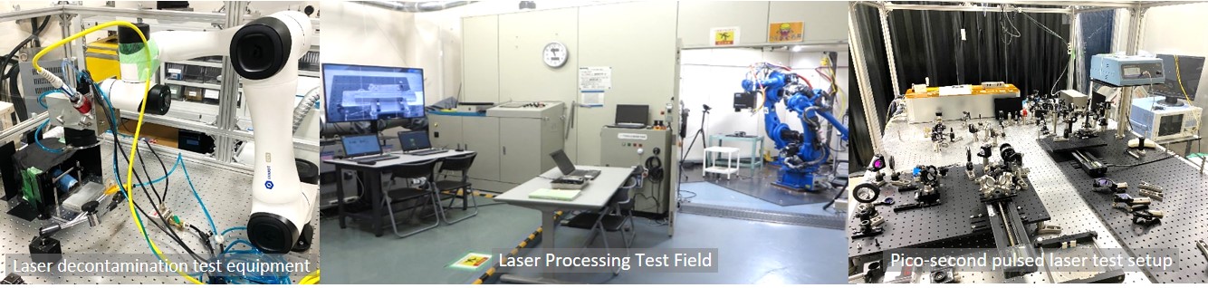
Figures II-1(1)[a] and [b] show a Galvano laser scanner system and a laser quenching experiment, respectively. The surface temperature transition of the test piece was observed by a thermo-monitor camera, as shown in Fig. II-1(1)[c].
Figure II-1(2) indicates the analytical results of the internal temperature transition of a test piece under two different cases. One is calculated under the high power and high sweep speed condition ([a] 5.0kW, 30mm/sec.), and the other is under the low power and low sweep speed condition ([b] 1.5kW, 1.5mm/sec.)
The comparison of these two cases has suggested that the lower laser power and the lower sweep speed condition (Fig. II-1(2)[b]) achieves deeper heat diffusion in the metal, expecting increased quenching depth.
Fig. II-1(1) Laser quenching experiment
Fig. II-1(2) 3D analitical results of temperature transition under two different laser irradiation cases
Shown in Figs. II-1(3)[a] and [b] are a micro-vickers hardening measurement result and a computer calculational temperature contour, both of which indicate the distributions at the perpendicular cross-section to the laser beam sweeping direction.
The comparison of both the Figs. [a] and [b] has revealed that the upper area is hardened by the sufficient temperature rise, whereas the lower area remains original hardness due to insufficient temperature rise.
To logically and precisely predict the laser quenching region, the CCT-curve diagram (Continuous cooling transformation) has been installed in the computer code, and the code classifies the metallurgical structure into Austenite, Martensite and Pearilte from the temperature history on the CCT-curve diagram.
Two cases of the metallurgical transformation calculational results are shown in Fig. II-1(4), where laser beams sweep from the right to the left side at different conditions. The blue, green and red regions stand for austenite, martensite and pearlite metalogical structure, respectively. The upper movie [a] clarifies the metal changes from austenite structure to martensite, which leads to successful hardening. The lower movie [b] indicates the metal changes from austenite structure to pearlite, which causes imperfect hardening, because of low cooling rate.
Thus, the JAEA computer code provides both the temperature distributions / transitions and the metallurgical transformation to clarify the hardening region, which helps the determination of appropriate laser quenching conditions such as laser power and sweep rate.
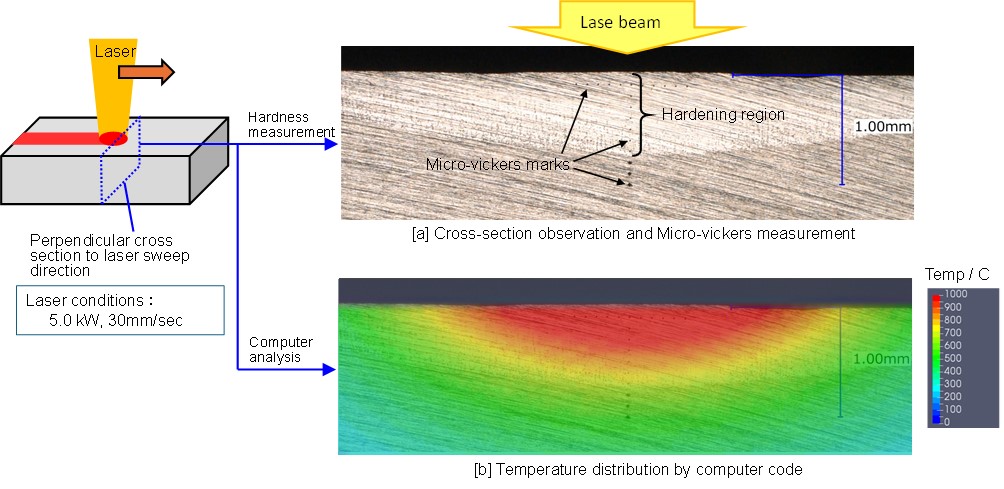
Fig. II-1(4) Analytical results of metallographic structure transformation during Laser quenching processing
Carbon fiber reinforced plastics (CFRP) are composite materials composed of carbon fiber and resin. CFRP combines the lightweight and high molding flexibility of resin with the high rigidity and strength of carbon fiber, offering a unique combination of properties. In recent years, CFRP have been utilized in the components of aircraft and automotive, and are now being employed in energy and infrastructure applications.
CFRP is classified into two categories. The first category comprises CFRP using thermosetting resin, which exhibits greater strength and rigidity than metal but is associated with prolonged molding times and non-recyclability. This type of CFRP is utilized in aerospace applications where mass production is not a priority. The second category encompasses CFRTP using thermoplastic resin, which displays reduced strength compared to CFRP but has a shorter molding time, enhanced economic viability, and recyclability due to the resin's melting point upon heating.
The objective of our research is to investigate the potential of laser processing to achieve minimal thermal effects on CFRTP (compact fiber reinforced thermoplastic resin), which is gaining interest in a number of fields, including automotive. Due to the low melting point of the thermoplastic resin utilized in CFRTP, processing must be conducted with minimal thermal effects. To this end, we are employing non-thermal processing techniques utilizing pulsed lasers with shorter pulse widths. We are conducting processing tests using a picosecond (10-12 seconds) pulse laser and performing preliminary experiments, including observations of the cutting of carbon fibers.
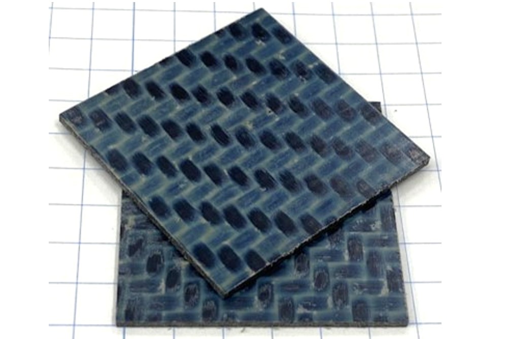
The sample selected was a CFRTP comprising carbon fiber and PPS with a thickness of 1 mm, which is a commonly utilized commercially available material (Fig. II-2(1)). Figure II-2(2)[a] depicts the surface of the sample following laser processing, exhibiting a molten region on the surface. In addition, as shown in Fig. II-2(2)[b], when the cross section was measured at a low magnification of 20 times (see the image in the light blue frame), a heat-affected zone (HAZ) was observed where the resin had vaporized approximately 1 mm horizontally in the direction of the laser beam. When measured at a higher magnification of 50x (see image in brown frame), it was confirmed that the carbon fiber was cut with a small kerf width.
As a future plan, we will explore laser irradiation conditions to further suppress the HAZ.
![[a] Surface photograph obtained following laser processing, [b] Cross-sectional image captured using a white confocal microscope](images/kenkyu-1-2_2-2ex.jpg)
JAEA Tsuruga comprehensive R&D center has conducted the research on the laser rust-resistance heat treatment in cooperation with the Nuclear Science Research Institute of JAEA (Radioactive waste management section 1). Laser heating on the metal surface forms the magnetite oxide layer that prevents red-rust development. Figure II-3(1) shows the magnetite oxide layers formation test by laser scanning irradiation, and the formation was investigated under various irradiation conditions.
Fig. II-3(1) Laser rust-resistance experiment(Magnetite layer formation test)
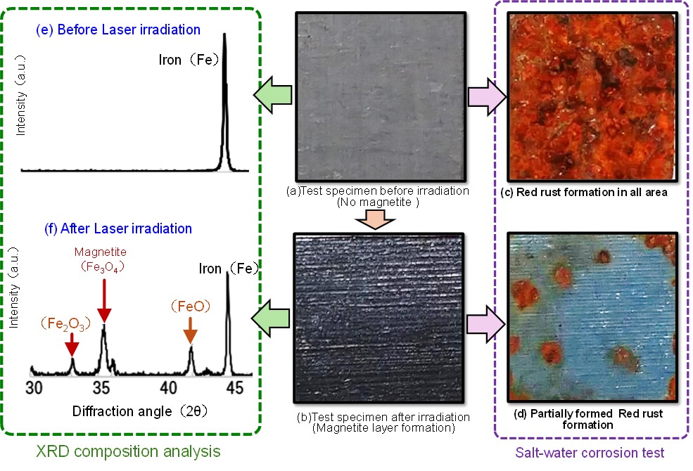
After the laser magnetite formation, its test pieces were examined by the corrosion test and the X-ray diffraction analysis, which are shown in Fig. II-3(2) with photos of the test pieces.
The photos (a) and (b) show a test piece before the laser irradiation and a magnetite formed test piece by the laser irradiation, respectively.
The corrosion test results, where the test pieces were subjected to salt-water spray for one month, are indicated in the photo (c), (d). The test piece with no magnetite was all covered with red-rust (c), whereas the red-rust was limitedly formed on the laser irradiated test piece (d). This corrosion test has suggested that the laser heating magnetite layer provides the resistance against red-rust developing.
The left two graphs(e), (f) of Fig. II-3(2) show the composition of each the test piece by the X-ray diffraction analysis. The laser heating forms the magnetite compositions such as Fe3O4, which supports the corrosion test result indicated in the photos (c), (d).
The magnetite layer requires to be uniform structure in order to enhance the rust-resistance performance and its durability, because lack of the uniformity develops cracks on the magnetite surface and deteriorate the rust-resistance property. One of the method to attain the uniformity is to flatten the temperature distribution on the surface during laser scanning irradiation. For this purpose, the temperature history has been investigated by the thermal conductance analysis of the computer code.
Figure II-3(3) presents the transition of the temperature distribution in the test piece during the laser scanning operation, in which the red-arrows of the test piece indicate the image of the laser scanning direction. The two central contours show the surface temperature transition, where the dotted square area of the lower contour is enlarged into the upper one. The vertical temperature distribution is shown in the right contour. These three contour movies synchronize for understanding the 3-dementional temperature transition.
This analysis has revealed the temperature history on the surface, which is useful to flatten the temperature distribution by adjusting laser conditions such as beam profile and scanning beam interval.
This study has suggested the prospects of the rust-resistance by laser heating, however, it's at an early R&D stage and necessitates future work to detrmine appropreate laser irradiation. The demonstration experiments are also required for actual use.
Fig. II-3(3) Temperature transition on metal surface by 3D thermal conduction computer analysis
The computer code has been developed to be applied for the joining of laser penetration plastic-resin materials.
In metal thermal processing, laser beam turns into heat at a metal surface, and the heat diffuses into the metal inside by thermal conduction. In laser penetration plastic-resin processing, however, laser beam travels into the material inside, and the beam changes to heat gradually here. With the progress of this plastic-resin heating, the interface of two plastic-resin materials are melted to be joined, as illustrated in Fig. II-4(1)[a].
The laser absorption model of the plastic-resin has been installed in the computer code to reveal the temperature distribution and its transition and to optimize laser conditions. Figure II-4(1)[b] indicates an analytical results of the changing process from the laser beam to the heat, leading to the temperature rising and the interface melting junction.
Fig. II-4(1) Analytical results of temperature distribution in Laser penetration plastic-resin
Actually, the interface of two materials is joined by laser sweeping operation. Figure II-4(2) shows an analytical result (movie) of the plastic-resin melting junction by the moving heat source. This movie clarifies the 3-dimensional temperature distribution and its transition with the laser moving from the left side to the right.
This calculational approach is believed to be applied for determining the suitable laser conditions for plastic-resin melting junction products. To confirm its accuracy, the analytical results will be compared with experimental data in the near future work.
Fig. II-4(2) Analytical results of temperature transition under Laser sweep irradiation
When conducting laser experiments, the plasma begins to ablate from the target surface as the laser intensity increases. Laser plasma physics examines the density and temperature conditions of the plasma when it interacts with the laser electromagnetic field. Recent theoretical predictions suggest that nonlinear quantum electrodynamics (QED) effects become significant during this interaction, particularly with the high-intensity electromagnetic fields generated by focusing a petawatt-class laser pulse. Some early experiments are starting to observe these effects.
Nonlinear QED is a theoretical model incorporating nonlinear interactions arising from a strong background electromagnetic field into quantum electrodynamics, which describes the behavior of particles such as electrons, positrons, and photons. In this model, electrons and positrons undergo state transitions by multiphoton absorption from the electromagnetic field. The scattering cross-section in nonlinear QED varies with the intensity of the background electromagnetic field, making high-intensity laser experiments crucial for verifying this phenomenon.
With the development of high-intensity lasers, nonlinear QED effects have garnered interest as a largely unexplored area of particle physics. Additionally, researchers in laser-plasma physics, who have long worked with high-intensity lasers, increasingly recognize the significance of nonlinear QED effects in laser-induced plasmas. This interdisciplinary field, which merges laser-plasma physics and particle physics, is called high-intensity field science or high-intensity laser science.
One of the scenarios that researchers in high-intensity field science aim to create is known as a nonlinear QED plasma.
This refers to a plasma composed of electrons, positrons, and photons, which forms in an avalanche-like manner within a strong laser electromagnetic field. The process involves three key phenomena: (1) High-energy photons are generated through nonlinear Compton scattering of electrons and positrons, (2) electron-positron pairs are created via the nonlinear Breit-Wheeler process involving photon annihilation, and (3) the electromagnetic field propagation is affected by QED vacuum polarization. As a result of those multiple scattering, these particles exhibit a wide momentum distribution. Laser plasma physicists are particularly interested in the collective phenomena associated with these novel physical processes.
As a theoretical model to explain the aforementioned nonlinear QED plasma, a transport equation has been proposed that includes the nonlinear QED scattering cross-section and decay rate in the collision term. This model substitutes the cross-section and decay rate, derived from nonlinear QED calculations, into the collision term of classical transport equations, such as the Boltzmann-type equations. A single scattering process of nonlinear QED is a phenomenon described by quantum field theory. However, it is not inherently obvious that the correct transport equation can be derived by simply substituting the cross-section and decay rate into the classical transport equation. Nonlinear QED particles need to adhere to the principles of nonlinear QED. Therefore, we are conducting theoretical research to develop a method to comprehensively derive the transport equation, including the collision term, from the foundations of nonlinear QED.
Although this issue originated from high-intensity field science, it is anticipated to contribute to deriving the transport equation for charged particles in low-intensity coherent electromagnetic fields. This research lays the groundwork for a theoretical foundation of quantum plasma collective phenomena. Additionally, since nonlinear QED also encompasses electromagnetic fields (photons), this study should yield the transport equation for photons. The stochastic ray tracing explored at our center models light propagation in classical optics. By comparing these approaches, we hope to uncover the essence of the classical-quantum correspondence of photon kinetic theory.
This activity is being carried out with the support of the Grant-in-Aid for Scientific Research (C) 24K06990 "Theoretical construction of a quantum transport model for nonlinear QED plasmas in a high-intense laser pulse."
We consider how accurately a laser beam can be represented as "rays” of light. In classical optics, it is widely accepted that light can be described as both rays and an optical wave. However, the ray representation is typically viewed as an approximation of the wave representation. While both representations have been established, there has yet to be a comprehensive explanation demonstrating their mathematical equivalence. In particle theory, the wave and particle nature of light (as described by the electromagnetic field) is supported by quantum field theory and we recognize the wave-particle duality of an electromagnetic field. Considering classical optics as the classical limit of quantum field theory, it seems reasonable to acknowledge the duality of an optical wave and rays. Exploring that duality, our center has developed a theoretical physics method called stochastic ray tracing.
We also provide practical context related to this topic. One method for representing the propagation of laser light is ray tracing, which our center employs for numerical simulations in laser processing. We utilize optical rays because the computational costs are lower than those with optical waves. In most laser processing experiments, high laser intensity is required on the target surface, necessitating the focusing of the laser light. In wave optics, focusing is treated as a result of diffraction phenomena. Conversely, the ray tracing method is an approximation that ignores the diffraction effects arising from the wave representation. Although the vicinity of the focusing point is critical in laser processing, the ray tracing method oversimplifies the situation. As a result, it is not well-suited for accurately expressing the focusing effect.
If we can effectively incorporate the diffraction phenomenon into the ray tracing method by reversing the conventional approach, we could claim to have constructed a ray representation mathematically equivalent to wave optics. Thus, our center proposed stochastic ray tracing, which utilizes stochastic rays that randomly fluctuate optical rays during the ray tracing computation [1]. In this context, the optical rays are assumed to propagate along a path defined by a specific stochastic process, with the ensemble of all stochastic rays representing a light beam. This model employs the slowly varying envelope approximation within the optical wave equation to induce beam-like behavior. Subsequent theoretical development relies on analytic calculation without further assumptions. We have demonstrated how the amplitude function of the optical wave affects beam spread and have established the stochastic differential equation (stochastic kinematics) that defines the aforementioned stochastic process, placing it at the core of the present ray tracing calculation. With this theoretical framework, we unified previously intuitive concepts—such as the uncertainty relation of beam spread—into a cohesive mathematical formula.
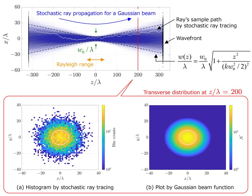
Figure II-6 illustrates a calculation of a Gaussian beam propagating in a vacuum through stochastic ray tracing. We learned that focusing straight optical rays gives us a focus "point," but this is not entirely accurate. If that were the case, any laser device could achieve infinite intensity. Wave optics teaches us that a Gaussian beam creates a focus spot area characterized by the Rayleigh range. Stochastic ray tracing effectively represents this situation, highlighting the distinction between scenarios with and without diffraction effects.
In reference [1], we explored the formulation of laser beam propagation in a vacuum; however, we are currently interpreting phenomena treated in wave optics into stochastic rays, broadening the Japan-original optical theory. Reference [1] has been recognized as an Editor's Pick in Optics Express.
Reference
[1] Keita Seto, “Stochastic ray tracing for Fresnel diffraction,” Optics Express 32 (10), p.p. 16999-17011 (2024)