I. Applied Laser technologies for decommissioning
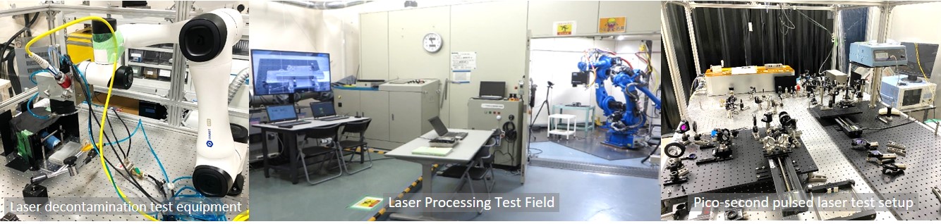
I-1 Laser cutting test equipment
I-3 Laser thermal processing analytical computer code
I-4 Laser decontamination using high-power density
I-5 Laser decontamination computer analysis (Metal surface de-lamination analysis)
Laser cutting technology can be employed for dismantling of components and piping under decommissioning, because the laser cutting has high-speed and non-contact processing performance in comparison with other cutting methods.
JAEA Tusruga comprehensive R&D center has a 10kW fiber laser oscillator, laser cutting irradiation heads, a Galvano laser scanner and a beam switcher. The beam switcher allows users to exchange these optical devises without installing and uninstalling. Figure I-1 shows the laser oscillator, a cutting head and its X-Y-Z axis cobtroller.
Fig. I-1 Laser cutting experimental system
Normally, laser cutting processing is conducted by both beam irradiation and assist gas flow. The laser beam melts a metal, and the assist gas flow removes the molten metal from its cutting kerf. In this cutting process, a laser irradiation head needs to be accessed to a cutting target to inject the assist gas to a kerf (Fig. I-2(b)).
However, decommissioning sites include complicated and narrow areas, as shown in the photo(a) of Fig. I-2, and therefore it's difficult to keep the irradiation head close to a cutting target. To employ the laser cutting method at decommissioning sites, a remote laser cutting technology is necessary, which is illustrated in Fig. I-2(c). This remote cutting raises a technical challenge "assist-gas-less cutting technique", because the distance between a laser irradiation head and a target prevents the assist gas reaching to the cutting kerf and then deteriorates cutting performance. To attain this remote-cutting method, the laser irradiation conditions need to be adjusted and improved, for example, laser beam profile optimization or wobbling operation adoption.
This is our new R&D approach for the laser cutting of decommissioning, and its progress will be uploaded in this website in the future.

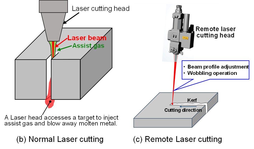
Fig. I-2 Remote Laser cutting concept
A three-dimensional laser analysis computer code has been developed to evaluate various kinds of laser thermal processing since 2020. The purpose of this code is to predict or understand physical phenomena in laser processing, and to support the determination of the appropriate laser irradiation conditions. The computer code includes heat-transfer, thermal-hydraulic and optical models below.
- Thermal conduction, thermal convection, radiation
- Metal melting, molten metal re-solidification, metal vaporization
- Molten metal flow, gas flow
- Surface tension, Marangoni convection, gravity
- Metal combustion heat
- Laser beam multi-reflection in kerf area
- Lambert–Beer law
- Sweep method (Liner, scanning, and wobbling)
- Beam profile (Top-flat, Gaussian and others, the profile is flexibly set up by users)
- Beam focusing
Figure I-3(1) illustrates the above-mentioned physical models for laser cutting.
This website describes examples of this computer code analytical results to evaluate laser cutting, laser decontamination and other laser thermal processing. The code's performance and applicability have been improved and upgraded, and the accuracy are also being verified by comparing with experimental data or theoretical solution.
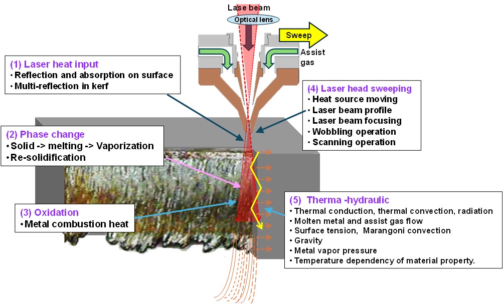
Figure I-3(2)[a], [b] shows analytical results of two kinds of laser cutting. The movie[a] indicates a 3D view of a full cutting case because of sufficient laser power and enough assist gas flow rate. However, insufficient assist gas flow rate causes incomplete cutting, shown in the movie[b], where low assist gas flow keeps the molten metal remained in the cutting kerf, and this remained molten metal disturbs cutting progress.
Fig. I-3(2) Laser cutting computer analysis
Shown in Fig. I-3(3) is a key-hole formation analysis obtained from the computer code. The metal surface, when heated by high power density laser, turns into molten metal and metal vapor immediately. The rapid pressure rising caused by metal vaporization releases molten metal from the metal surface, and consequently a deep (key) hole develops into the surface.
Three movies of the key-hole formation process indicate the distributions of the temperature, the VOF (Volume of fluid) and the laser energy absorption, which are significant physical factors to understand the key-hole development. This key-hole formation analysis isalso an important to evaluate laser cutting, because its development is one of the fundamental phenomenon of the cutting processing. This analytical result will be confirmed by the depth measurement and the high-speed camera observation in key-hole development experiments in the future.
Fig. I-3(3) Key-hole formation computer 3D analysis
The objective of our research is to investigate the efficacy of laser decontamination techniques for the decommissioning of nuclear reactor facilities. In the process of decommissioning nuclear reactors, the decontamination of radioactive waste can result in a notable reduction in the cost of disposal, due to the diminished volume of radioactive waste. The utilization of mechanical and chemical decontamination techniques often causes the exposure of workers to radiation and the generation of considerable quantities of secondary waste. In contrast, the implementation of a decontamination approach based on laser technology can be conducted remotely, thereby minimizing worker exposure. Furthermore, because of the non-contact processing of this decontamination method, it can markedly reduce the generation of secondary waste.
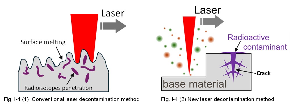
In long-term operated nuclear reactor facilities, cracks have developed on the surfaces of their components and piping, therefore some of radioactive materials have remained in the cracks.
Conventional laser decontamination methods, the power of which is relatively low, tends to melt the base metal surface, allowing radioisotopes to penetrate in the melting region and decreasing a decontamination efficiency, as shown in Fig. I-4(1). To achieve a high decontamination efficiency, the base metal surface requires to be removed together with the cracks, which is illustrated in Fig. I-4(2).
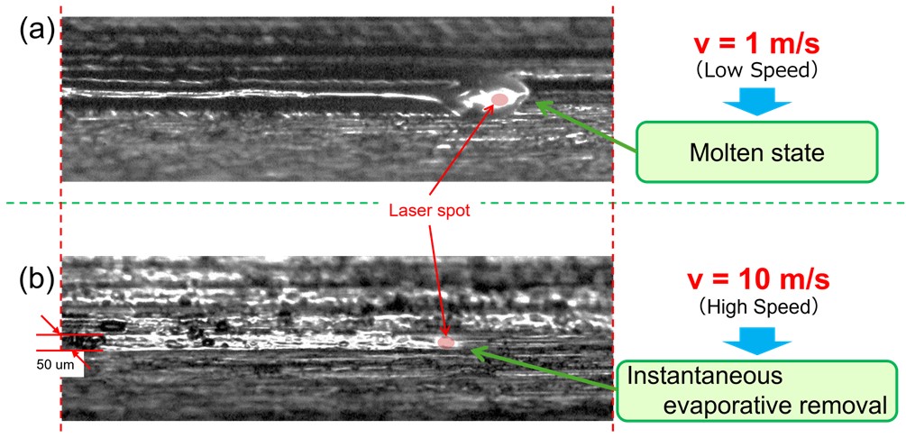
In our study, this new laser decontamination method has been developed with largely increased (high) power density laser beam by focusing a CW laser onto a small spot (approx. 50μm in dia.). The increased (high) power density laser irradiation instantaneously evaporates and removes the metal surface with cracks and then decrease the radioisotopes penetration effect. The decontamination tests have been carried out under this condition at various scanning speeds.
Figures I-4(3) and (4) show a movie of a test piece during the laser irradiation and images observed by a high-speed video camera at different scanning speeds of (a) v = 1 m/s and (b) v = 10 m/s , respectively. At a scanning speed of 1 m/s, the high-speed video camera has revealed that the surface metal melted around the laser irradiation area, forming a droplet that moved with the laser beam spot and a long-melted tail as it moved. These molten droplet and molten tails trap radioisotopes along the laser irradiation during laser decontamination. In contrast, at a high scanning speed of 10 m/s, the video camera has shown that the metal surface evaporated instantaneously without melting, leading to no radioisotopes penetration in the molten metal.
Our experimental result has suggested that the increased power-density and the high-speed scanning conditions are expected to attain high decontamination performance.
The research is currently being conducted to further enhance the efficacy and to investigate potential applications of this method. We plan to continue decontamination tests and develop optimal laser irradiation conditions for contaminated objects in various situations.
Fig. I-4(3) Laser decontamination experiment (Metal surface removal test)
Laser decontamination is a method to remove radioactive substances attached on metal surfaces or in cracks by high-speed laser scanning heating. The scanning motion image is shown in Fig. I-5(1)[a]. This laser heating induces the metal surface melting and vaporization, and separates radioactive substances together with the metal vapor from the surface. After that, the separated radioactive substances are trapped by a dust collector.
The computer analysis, shown in Fig. I-5(1)[b], visualizes this metal surface de-lamination by melting and vaporization under laser scanning irradiation from the right side to the left. The calculational area of Fig. [b] is in the bule square region of Fig. [a].
Fig. I-5(1) Laser decontamination analysis (Metal surface de-lamination)
Details of this surface de-lamination process are shown in Fig. I-5(2)[a] and [b], where the beam passes from the rear to the front (Fig. [a]), and Fig. [b] indicates the metal surface phase-change in the vertical cross-section of the blue square area at the central line of Fig. [a].
With the laser beam approaching to the central line, the temperature of the metal surface rises, and the surface begins to melt, leading to vaporization of the upper molten area. After the laser beam going trough the central line, the molten metal begins to solidify gradually and the molten area disappears eventually.
This computer code visualizes the phase-transition, which is useful to understand the phenomenon on the metal surface induced by moving laser heat source and to detreimine optimal laser irradiation conditions.
Fig. I-5(2) Metal surface phase transition during laser beam passing on de-lamination process