


Mono-energetic Neutron Calibration Fields
Mono-energetic neutron calibration fields have been developed at the Facility of Radiation Standards (FRS) of Japan Atomic Energy Agency (JAEA) using a 4MV Van-de-Graaff (Pelletron) accelerator. There are 10 points available between 8 keV and 19 MeV, which cover the energies specified in ISO 8529-1, for the energy response test of neutron dosimeters.

Energy points and nuclear reactions for their neutron productions.
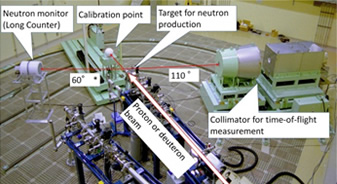
Irradiation room.
Reference
- 1. Y. Shikaze et al., Radiat. Prot. Dosim. 126 (2007) 163.
- 2. Y. Shikaze et al., J. Nucl. Sci. Tech. Suppl. 5 (2008) 209.
Thermal Neutron Calibration Fields using a Graphite Pile
Thermal neutron fields have been established at FRS using moderated neutrons from a graphite pile with a 252Cf neutron source. The graphite pile has a dimension of 1.50 m(W) × 1.64 m(L) × 1.50 m(H). The calibration points, #1 and #2 are set at 40 cm from the graphite surface.
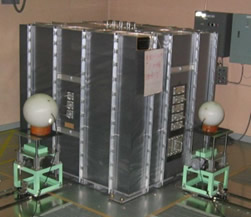
A photograph of the graphite pile.
| Calibration point | H*(10) [mSv-h-1] |
Hp(10) [mSv-h-1] |
| #1 | 19.9 | 21.4 |
| #2 | 25.3 | 27.2 |
Reference
- 1. M.Yoshizawa et. al., http://www1.bipm.org/cc/CCRI(III)/Allowed/15/CCRI(III)03-07.pdf
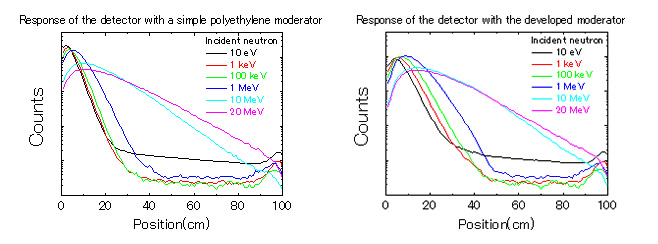
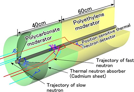
Moderated-type Neutron Detector for Transferring Standards of Calibration Fields with Broad Spectra
To establish the traceability of calibration fields having broad, continuous neutron spectra in the usual workplace, a standard neutron detector applicable for a wide energy range was developed. The moderator structure for the detector was optimized using the Monte Carlo code MCNP-4B. The detector consists of a cylindrical moderator and position-sensitive thermal neutron counter, and it obtains energy spectra from thermal neutron distribution along its cylindrical axis. The structure of the moderator was improved using a low hydrogen density material on one end and a high hydrogen density on the other, and by inserting a neutron absorber that eliminates thermal neutron diffusion. This design improves the energy resolution of the detector, especially for low-energy neutrons from a few keV to 100 keV. The designed detector can be applied to the measurement of energy spectra over a neutron energy range from a few keV to 20 MeV.
Reference
- 1. Y. Tanimura et. al., J. Nucl. Sci. Tech. Suppl. 4, 411 (2004).
- 2. Y. Tanimura et. al., Nucl. Instrum. Meth. A547, 592 (2005).
Development of the Monte Carlo code system (MCNP-ANT)
The MCNP-ANT (MCNP for Accelerator Neutron Target) code system consists of a newly developed Monte Carlo program for calculating the transport of charged particles and neutron production, and incorporates an existing neutron transport code, MCNP version 4C. The newly developed program can deal with protons and deuterons up to an energy of 4MeV as incident charged particle. The slowing down and scattering of charged particles in matter are simulated by the method used in the SRIM (TRIM) program, which is one of the most widely used programs for transport calculation of ions in matter. The history of resultant recoil particles from the interaction is also traced. The reactions of 2H(d,n)3He, 3H(d,n)4He, 3H(p,n)3He, 7Li(p,n)7Be, 7Li(p,n)7Be* and 45Sc(p,n)45Ti are available in the code system. The results of the calculations for typical mono-energetic neutron calibration fields indicate generally good agreement with the experimental ones as shown in Figure 1 and Table 1.
| Source Reaction |
Target/ Backing |
Neutron energy |
Energy spread | Neutron fluence at 10cm (cm-2・μC-1) |
||
|---|---|---|---|---|---|---|
| MCNP-ANT | Baba et.al | MCNP-ANT | Baba et.al | |||
| 3H(d,n)4He | Ti-T / Cu | 15 MeV | 400 keV | ~500 keV | 1.4×10⁵ | 8.0×10⁴ |
| 7Li(p,n)7Be | LiF / Pt | 550 keV | 55 keV | ~50 keV | 2.5×10⁴ | 3.2×10⁴ |
| 7Li(p,n)7Be | LiF / Pt | 250 keV | 60 keV | ~50 keV | 6.5×10³ | 1.0×10⁴ |

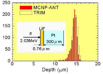
Figure 1 Mono-energetic neutron spectra calculated by the MCNP-ANT code in comparison with the experimental spectra measured by the TOF method (Baba et.al.)
Reference
- 1. M. Yoshizawa et. al., 10th Intl. Congress of IRPA (CD-ROM), 4p. (2000)
- 2. M. Yoshizawa et. al., J. Nucl. Sci. and Technol., Suppl. 2, p.1240 (2002)
Development of a Radiation Meter for Home Use
We developed a simple but reliable radiation meter for the general public. The most important component of the radiation meter is the radiation sensor, which should have stable performance and a long lifetime. Therefore, the photon detection performances of three types of the radiation sensors, a silicon pin photodiode, CdTe detector, and Geiger-Mueller (G-M) counter, have been studied both experimentally in photon calibration fields and by Monte Carlo simulations. Their energy responses to ambient dose equivalent H*(10) were evaluated as shown in Figure 2. The silicon photodiode was employed as the sensor because it was superior to the G-M counter and CdTe detector in terms of both performance and stability.
The fabricated radiation meter consists of several electrical circuits, as shown in Figure 3. To achieve low cost, no special components are used, but all components are available in the market. The meter notifies radiation detection by both sound and light and displays the average level of radiation during the previous four-minute time period. This radiation meter employs a graphical radiation measurement display and some illustrations as shown in Figure 4. This simple meter allows anyone to understand the radiation level quickly and easily.
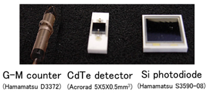
Fig.1 Radiation sensors
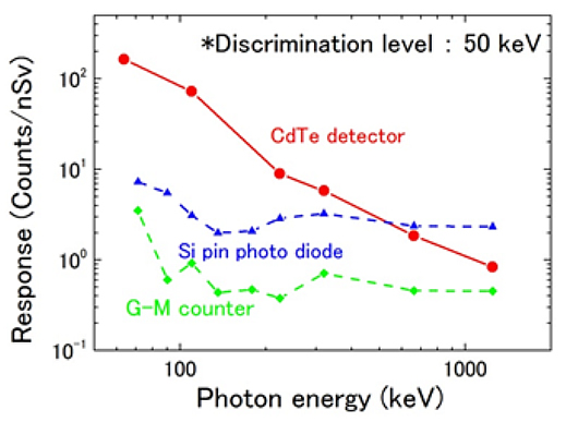
Fig.2 Characteristics of the sensors
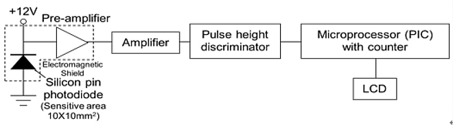
Fig.3 Schematic diagram of the radiation meter
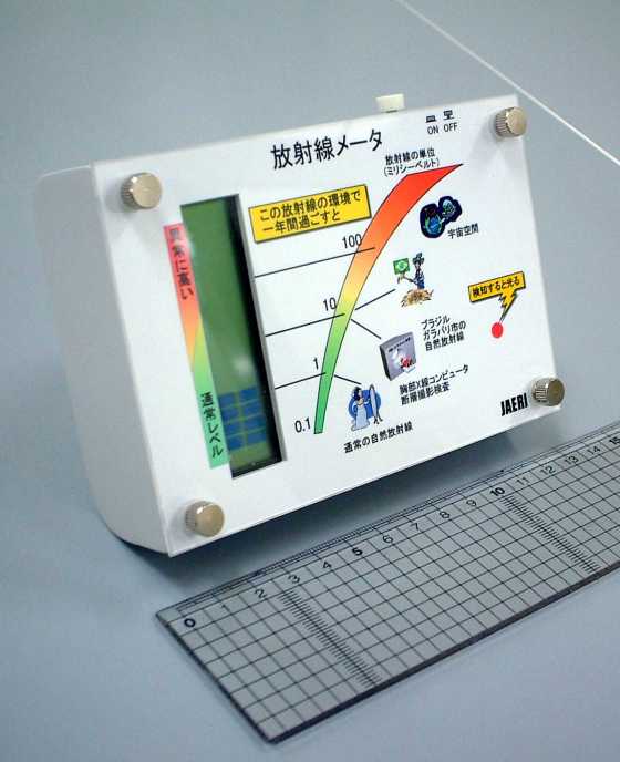
Fig.4 Photograph of the developed radiation meter