|
[Supplementary explanation] Outline of partial loss of coolant flow test Figure 1 shows the schematic diagram of the primary cooling system in the HTTR. The heat generated in the reactor core of the HTTR is removed by the helium gas as a primary coolant circulating in the primary cooling system, transferred to the pressurized water as a secondary coolant in the primary pressurized water cooler (PPWC) and released finally to the atmosphere in the pressurized water air cooler. Three gas circulators are located around the PPWC to circulate the primary coolant. One or two out of three gas circulators are stopped and the primary coolant flow rate is reduced down to one-third of the rated flow rate in the partial loss of coolant flow test. The intermediate heat exchanger located with the PPWC in parallel in the primary cooling system is not operating in this test. The abnormal coolant flow reduction is detected automatically by the reactor protection system in the HTTR usual operation. The partial loss of coolant flow test was performed under the condition of the ATWS (Anticipated Transient without Scram) such that the reactor scram does not occur. The tests were systematically performed so as to stop one or two gas circulators under each four initial conditions of the reactor power in the region from 30% (9MW) to 100% (30MW). 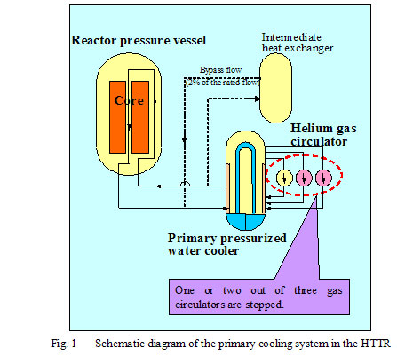  Figure 3 shows the reactor behavior during the partial loss of coolant flow test by stopping two out of three gas circulators at the initial reactor power of 100% (30MW). In this case, the ability of the heat removal in the reactor decreases due to the reduction of the coolant flow. But the reactor power decreases slowly due to the excellent and inherent safety characteristics of the HTGR and becomes to the stable state. The pre-analysis result shows the good agreement with the experiment result. 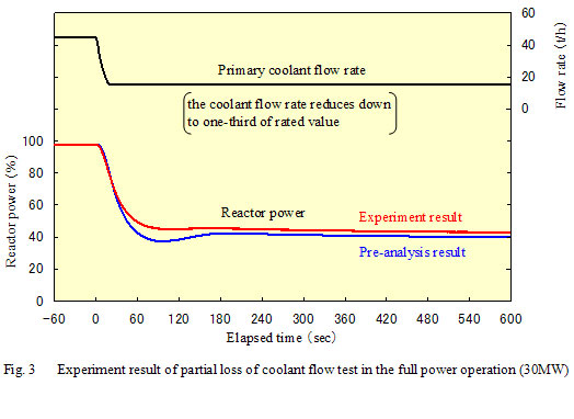 (BACK) |